-40%
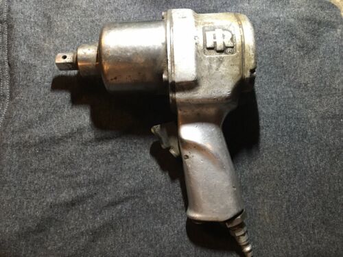
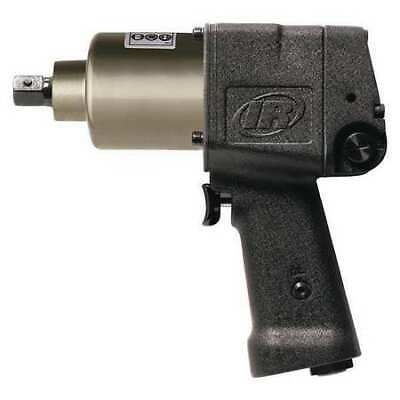
INGERSOLL-RAND 406 Vintage Tool Mod. A 2718803 Air Impact Wrench USA 🇺🇸 Made
$ 18.47
- Description
- Size Guide
Description
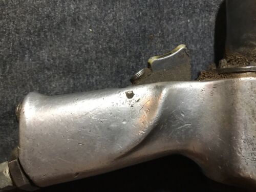
🚨 INGERSOLL-RAND 406 Vintage Tool Mod. A 2718803 Air Impact 🔧 Wrench USA 🇺🇸 Made. 🔥 this impact wrench was used by my grandfather, it’s in used condition and is made from an era in which the quality of tools was much higher than that of today. Condition is “Used”. And there is natural wear and tear, scratches that are pictured in the listing, and it needs to be thoroughly cleaned, however that may lead to resting. Malta meal goal is to reserve it and it’s original quality. Shipped with PriorityThis invention relates to impact tools, and more particularly to portable impact: toolsof the type having a motor: driven: hammer adapted to deliver to an anvil a constant. turningz'fo'ce at:- low torque loads: and. at. high torque loads, axseries of: high velocity rotaryblow's for rotatingznuts, bolts or similar'workpiecea.
In tools of: this-type; and especially tools used in assembly line operations, it is-highlydesirable that the tool be simple in -design andicapableof operating relatively troublefree for long periods of'time.
It is accordingly oneobject of this invention to provide an-impact tool of relatively simple and compact design.
Further objects will become obvious from the following description anddrawings in which;
Figure l@is-a verticaL-elevation, partly in' section, showing .-a preferred embodiment of the invention,
Fig. 2 isa cross-sectional view taken through Fig. 1 along. the? line 2 2'looking inthe direction of the arrows, and
Figs. Sand 4; are similar to-Figg 2 but show different operative positions of the-hammer relative tothe anvil.
Referring. to Fig. l of the drawings,.a.preferred form of the impact toolis-shown as comprising, in general, a casing 8- housing amotor' driven carrier 9 on which is eccentrically pivoteda hammer 10 having alongitudinal jaw, or. lug, 16 arranged tostrikea series of blowson a jaw 18 onan anvil; 12,.torotatea workpiece.14.
Thedriving connection between. the motor andthe carrier 9 includesadriver 28positivelyiconnected-to the motor 15 and. bearing; against a lever means 30 on the hammer 1.0 such that there is a lever, or carnming force tending constantly torotatethe carrier 9 and hammer 10 about the anvil1-2 and-to rock. the hammer lil about its axis 20 outof engagement with the anvil 12.. Thusthe driver. 287-leverconnection serves1notonly as a. driver, a
but additionally asameans-for disengaging the hammer Iii-from the. anvil 12 immediately after ahammer blow isstruck. sothat thecarrier 9 is free. to be: quickly accelerated to a high velocity 'prior to the hammer 10;strikingthe next blow. Duringthis free movement of the carrier 9, the hammer 10 is positively rocked. about its axis-20 into aposition toengage the anvil by cammeans 22,- 24 on the-hammer ltlandanv-iLlZ, respectively.-
Referring now in greater detail tothe construction of the tool, vthe'motor: 15--.is; of: the type, such as an air motor, thatcan be loaded until it stalls-without damage to the motor. This type.- ofi motor isrequired because during every hammer-cycle of theimpactingportion of a-tighteningoperation;.thehammer- 10;.andhence the motor- 15, isoften brought to substantially a complete halt atthe time-of impact ofi the hammer10- on theanvil 12,. and then-accelerated. to maximum speedprior to'the next blow. connectedrasiby spline's' 3*1'1,.to:the: motor shaft 32:is
the. driver 28;W.hichi includesai pair of arms arrangedto exertza drivingtand rockingqforcaon the lever: 30 integral .withttheghamqle't .10: "EheadrivenZS shownds inthe-f'orm 2,718,803 Patented Sept. 27, 1955 of a plate with a boss 29 for connection with the motor shaft 32 and has a pair of integral radially extending arms 34 and 36 forming a V-shaped area therebetween. The lever block 30 shown is roughly frusto-conical in cross-section and is located loosely with this V-shaped area with surfaces 38 and 40 arranged to be contacted by the arms 34 and 36, respectively. These surfaces are arranged, such that the contacted surface '(e. g., surface 38- Fig. 2) is inclined with respect to the surface of thecontacting driver arm (e. g., surface 41 Fig. 2). Inasmuch as the pivotal axis 20 of the hammer 10is also the axis of the lever block 30, the force exerted by the driver 28011 the lever block 30 atthis time not only tends to rotate the carrier 9, but also pivot the hammer 10 about the axis 20 to disengage the hammer 10 from the anvil 12. 112118 to be noted that the relative inclination between the lever and driver surfaces 38 and 41, respectively, is such that the hammer is pivoted in the same direction as the direction of rotation of the driver 28.
The magnitudeof the disengaging force for any given motor torque is determined by the ratio of the lever arms E and F (see'Fig. 3). The lever arm F is the distance from'the driver axis to the contact point between the arm 34and surface 38; the lever arm E is the perpendicular distance between the axis 26 and a line G perpendicular to line F and'passing through said contact point. In this connection it is to be noted that at least a portion of; the leverblock surface 38 extends outwardly beyond the axis 2! or is radially more distant from the axis of the'driver, and that the driver arm contacts this portion only of the lever30. Thus the rotation force exerted along the line G lies at alltimes outside of the axis 20.
IiTaddltlOH to exerting a cam-force tendingto rock the hammer 10 about its axis 20, the driver 28 also drives, or rotates, the hammer about a more central axis the axis 27 of the carrier. In furtheranceto this end, the
hammer 10is mounted on and rotatedwith the carrier'9i.
Thecarrier'9 comprises a pair of end plates 52 and 54 rotatably mounted on the driver 28 and anvil stem 56, respectively, and a semi-circular connecting wall portion 58 having its center located approximately 180, or diametrically opposite, from the transverse center of the relatively heavy jaw portion of the hammer 10 such that the wall serves additionally as a counterweight.
The hammer 10 which is roughtly tubular in shape is eccentrically mounted on a pin 60 extending through the endzplate 52 and 54; The bore 61 of the hammer shown hasthe same radius for approximately 250 degrees, the remaining are 63*0f' degrees is of a somewhat greater radius'and with a different center point, thus a pair of longitudinal shoulders, or jaws, 16 and 62 are provided for engagement with the anvil jaws 18 and 64, respectively, The shape of the periphery of the bore arc por tion 63and, within relatively broad limits, the lengths of the arms are'relatively unimportant from the tool operation standpoint, however, the jaws 18 and 64 are formed suchthat the striking jaw is substantially radial to theaxis of the anvil'lZ at'the time of the blow (see Fig. 2) The depth of the jaws 16 and 62 is such that when the ham mer is pivoted by the driver, the contacting hammer jaw moves clear of the contacted anvil jaw (see Fig. 3).
The anvil 12 is in the form of a cylinder with a recess 66 at the rearward end in which the motor shaft 32 is piloted, whereas the forward end, or stem portion 56 extends through the front end of the casing 8 and is adapted to fit a socket. 68 or similar element for connection with a workpiece. Located along the rearward end portion of the anvil 12 and positionedwithin the'hammerbore. 61 is; a radially extending lug 7t having'a radius only; slightly. more. than the radius of the 250 portiorrof the hammer bore 61 and being approximately l05 degrees in length. This lug 70 provides the two shoulders, or anvil jaws, 18 and 64 the faces of which are substantially radial to the anvil axis so that when a hammer blow is struck the contacting surfacese. g., see jaws 16 and 18 in Figs. 2are in parallelism and full surface contact is obtained. Of course these jaw surfaces may be inclined slightly from the radial to obtain a slight declutching or clutching effect where such effect is deemed desirable.
The outer periphery of the lug 70 serves additionally as the'cam means 24 which cooperates with the cam means, or surfaces, 22 of the hammer bore 61 to rock the hammer about the pin 60 and place a hammer jaw in full alignment with an anvil jaw prior to a hammer blow. It is to be understood that although substantially circular cam surfaces are shown for the cams 30 and 24, such shape is not necessary to the operation of the tool. That is, a slightly eccentric shape may be used so long as there is relatively shockless mating of the cam surfaces 22 and 24 after release of the lever 30 (as occurs at approximately the hammer and anvil position shown in Fig. 4), and the hammer is pivoted into clutching position with the anvilthe position shown in Fig. 2before the trailing edge of the hammer cam surface 22 leaves the anvil cam surface 24.
Reviewing briefly the operation of the impact'tool and assuming the tool has been mounted on a workpiece, such as a nut 14 shown in Fig. l, and assuming further that the hammer is rotated clockwise, as viewed in Fig. 2, the various elements of the tool will take the positions shown in Fig. 2 with the hammer shoulder 16 contacting the anvil shoulder 18 and the driver arm 34 contacting the lever surface 38. During any period when there is very little resistance to rotation of the anvil 12, as when the nut 14 is being threaded along the bolt 73 and prior to seating against a plate 74, the camming force exerted by the driver arm 34 and lever 30 tending to pivot the hammer out of engagement with the anvil is normally not suflicient to overcome the frictional force between the anvil and hammer jaws 18 and 16, respectively. Accordingly, the hammer and anvil 12 will remain engaged so that the nut 14 is rotated constantly until the resistance to rotation increases above some predetermined value.
When the resistance to rotation of the anvil exceeds said predetermined value, the driver arm 34 acting on the lever 30 will rock the hammer about its axis 20 into the position shown in Fig. 3 with the hammer shoulder 16 moved out of alignment with the anvil shoulder 18. The motor will then quickly accelerate the carrier 9 through 360 degrees such that the hammer is moving at substantially the maximum speed of rotation of the motor prior to striking the next hammer blow. During this relatively free rotation of the carrier 9, the hammer cam surface 22 comes in contact with the cam surface 24 (see Fig. 4) and the hammer is gradually and positively pivoted about its axis against the pivotal force exerted by the driver arm 34 and lever so that the hammer shoulder 16 is moved into alignment with the anvil shoulder 18 immediately prior to impact between these two shoulders.
The hammer striking a high velocity blow on the anvil, rotates the workpiece until, again, the pivotal force exerted by the arm 34 and lever 30 overcomes the frictional force between the hammer and anvil shoulders so that the hammer is rocked about its eccentric axis 20 and out of engagement with the anvil. It is to be understood that the time of disengagement of the hammer from the anvil will vary somewhat, depending upon the degree of tightness of the work. For example, when the work is relatively loose, the hammer will remain engaged with the anvil and rotate through several degrees prior to disengaging, whereas when thework is relatively tight there is a tendency for the hammer to rebound after a blow is struck, and the hammer will be disengaged from the anvil during such rebound.
The operation of the tool in the counterclockwise direction is identical with clockwise operation, except of course, impacting now occurs between the jaws 62 and 64 and the driving and declutching forces are exerted by arm 36 on surface 40.
While I have shown and described a specific form of my invention, it is to be understood that various changes and modifications may be made without departing from the spirit of the invention as set forth in the appended claims.
I claim:
1. A rotary impact tool comprising a motor, a rotatable carrier, an anvil, hammer element surrounding the anvil and pivotally mounted on the carrier on an axis eccentric to the carrier axis, clutch means on the hammer and anvil alternately engaged and disengaged during the impacting period of an operating cycle to rotate the anvil, cam means on the hammer and anvil arranged to contact during every hammer rotation to pivot positively the hammer about its eccentric axis to move said clutch means into engaging alignment immediately prior to contact therebetween, and a driving connection between motor and carrier for rotating the hammer and carrier about the carrier axis, said driving connection including a lever device constantly tending to pivot the hammer about its eccentric axis to disengage said clutch means.
2. A rotary impact tool comprising a motor, a carrier, an anvil having a shoulder on its periphery, a hammer element pivotally mounted on the carrier on an eccentric axis and having a bore surrounding the anvil, said bore being shaped to provide a shoulder adapted to engage said anvil shoulder, cam means on the hammer and anvil arranged to contact during every hammer rotation to rotate positively the hammer about'its eccentric axis to move the hammer shoulder into engaging alignment with the .anvil shoulder immediately prior to contact therebetween, and a driving connection between the motor and the carrier for rotating the hammer and carrier about the carrier axis, said driving connection including a lever device constantly tending to pivot the hammer about its eccentric axis to move the hammer shoulder out of alignment with the anvil shoulder for disengaging the hammer from the anvil after contact between said shoulders.
3. A rotary impact tool comprising a motor, a carrier, an anvil having a shoulder on the periphery thereof, a hammer element pivotally mounted on the carrier on an eccentric axis and having a bore surrounding the anvil, the surface of said bore being shaped to provide a shoulder adapted to engage said anvil shoulder and to provide a cam for engagement with the anvil shoulder during at least every 360 degrees of rotation of the hammer for pivoting the hammer about its eccentric axis to move the hammer shoulder into engaging alignment with the anvil shoulder immediately prior to contact therebetween, and a driving connection between the motor and the carrier for rotating the hammer and carrier about the carrier axis, said driving connection including a lever device constantly tending to pivot the hammer about its eccentric axis to move the hammer shoulder out of alignment with the anvil shoulder.
4. A rotary impact tool comprising, a motor, a carrier, an anvil, a hammer element surrounding the anvil and movably mounted on the carrier, clutch means on the hammer and anvil engaged and disengaged alternately during the impacting period of an operating cycle to rotate the anvil, cam means on the hammer and anvil arranged to contact during every hammer rotation to rotate positively the hammer relative to the carrier to move said clutch means into engaged alignment immediately prior to contact therebetween, a driving connection between the motor and the carrier for rotating the hammer and carrier about the carrier axis, said driving connection including a lever on the hammer and an arm connected to and rotated by the motor and constantly bearing against the lever to exert a force tending to pivot the hammer relative to the carrier to disengage said clutch means.
5. A rotary impact tool comprising, a motor, a carrier, an anvil, a hammer element surrounding the anvil and pivotally mounted on the carrier, clutch means on the hammer and anvil engaged and disengaged alternately during the impacting period of an operating cycle to rotate the anvil, cam means on the hammer and anvil arranged to contact during every hammer rotation to rotate positively the hammer relative to the carrier to move said clutch means into engaged alignment immediately prior to contacting therebetween, a driving connection between the motor and the carrier for rotating the hammer and carrier about the carrier axis, said driving connection including a surface on the hammer having at least a portion thereof extending outwardly beyond the hammer pivotal axis, and an arm connected to be rotated by the motor and constantly bearing against said portion of the hammer surface to exert a force tending to pivot the hammer about its pivotal axis to disengage the hammer from the anvil.
6. A rotary impact tool comprising a motor, a carrier including end plates and a connecting member, an anvil having a shoulder, a hammer element pivotally mounted on the carrier on an eccentric axis located approximately opposite the transverse center of said connecting member and having a bore surrounding the anvil, said hammer element being somewhat enlarged at the portion adjacent the eccentric axis and the bore being shaped to provide a shoulder adapted to engage and disengage with the anvil shoulder during the impacting period of an operating cycle to rotate the anvil, cam means on the bore of the hammer for engagement with the anvil during at least every 360 degrees of rotation of the hammer to rotate positively the hammer about its eccentric axis to move the hammer shoulder into engaging alignment with the anvil shoulder immediately prior to contact therebetween, and a driving connection between the motor and the carrier for rotating the hammer and carrier about the carrier axis, said driving connection including a device constantly tending to pivot the hammer about its eccentric axis to disengage the hammer from the anvil.
References Cited in the file of this patent UNITED STATES PATENTS 2,256,496 Robinson Sept. 23, 1941 2,514,914 Van Sittert July 11, 1950 2,539,678 Thomas Jan. 30, 1951 2,580,607 Schmid Jan. 1, 1952 2,663,395 Schmid Dec. 22, 1953 FOREIGN PATENTS 466,638 Canada July 18,- 1950
