-40%
1/2 VW (Half VW) Engine Conversion Plans for Ultralight or LSA Aircraft
$ 13.2
- Description
- Size Guide
Description
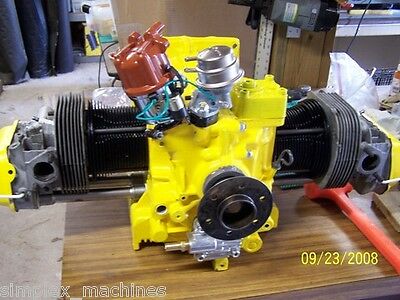
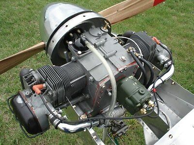
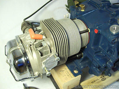
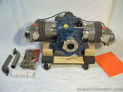
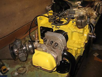
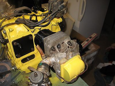
1/2 VW Engine PlansLooking for a way to mount a 4-stroke engine to your ultralight or light aircraft? The economic solution is to take a full-case Volkswagon engine and modify it from four cylinders to using only the front two! There are various plans available from different sources for converting a full VW engine to a 1/2 VW engine, but they all, including our plans, specify removing the rear 2 cylinders, cutting the crankshaft and cam, and cutting the cylinder heads. There are then a multitude of various other modifications needed to seal up new openings created during the conversion and keep the engine leak free. Our new plans include over 30 pages of written instructions with additional pages of figures and drawings. There are even full scale templates for making the proper parts.The detailed plans and drawings which take you all the way through the conversion process to actually starting and running your creation. The plans come spiral bound in an easy to understand format printed on good glossy paper with vibrant color photos.
Keep in mind that our plans call for using the entire case as this is the easier method and in many ways the preferred method for conversion. They do NOT specify how to do the
cut-case
type conversation.
So why should you build a 1/2 VW Engine? Here are few good reasons:
Parts are low cost and available via the internet or sometimes can be purchased in your home town.
The engine is relatively lightweight. There is no expensive or heavy reduction drive or exhaust system to mount. Most of the time the crankcase is made of magnesium which is 33% lighter than comparable aluminum. If you build it well your engine will weigh 85-90 lbs. Engine HP can be from 28-37 hp depending on the internal parts used.
The cylinders are aircooled, though truth be told most of the cooling comes from the oil. This means you don’t have to worry about a heavy or complex liquid cooling system.
Below is a list of the content provided in our plans:
Benefits of the Full-Case:
Understanding the Plans:
History of Plans:
Work Area and Conditions:
Engine Selection:
Operating Specs:
Ignition
Carburetor Type
Sealants and Lubricants:
Parts List:
Suppliers:
Tools and Services Needed
STEPS for Disassembly and Parts Fabrication
Step 1 - Drain oil, remove parts, separate the case
1.1 - Clean the case and all parts
Step 2 - Inspect the Crank Case
Step 3 – Prepare the Case
Step 4 - Painting the Engine
Step 5 - Altering the Case
5.1- Install studs and oil pickup
5.2- Tap case for oil temp probe
5.3- Bypass the oil cooler
5.4- Plug rear main feed and plug lifter bores
5.5 – Make case block off plates
Step 6 - Cutting and altering the cylinder heads
6.1 - Clean and inspect Cylinder Heads
6.2- Remove and discard valves
6.3- Install new valves
6.4- Cut and drill the heads
6.5 - Create the intake tubes
6.6 - Welding the heads
Step 7 - Alter Rocker Arms, Shafts and Covers
7.1 - Cut and weld the rocker covers
7.2 - Make exact measurements
7.3 - Cut the rocker arm shaft
Step 8 - Crankshaft cutting and altering
8.1 - Disassembly and inspection
8.2- Cut the crankshaft
8.3- Make the counterweights
8.4 -Weld the counterweights and oil feed
Step 9- Machine the Crankshaft
Step 10- Dynamic balancing
Step 11- Mounting a prop Hub
Step 12 - Cut the Camshaft
Step 13 - Creating the exhaust pipes
STEPS For Re-assembly Of The Engine
Step 1 - Crankshaft Assembly
1.1
– Crankshaft Preparation
1.2 – Heated Crankshaft Assembly
Step 2 - Prop Hub Installation
Explanation of Installation
2. 1 – Heat and install the prop hub
2.2 - Install hub bolt
2.3 - Drill hub bolt
2.4 - Double check measurements
2.5 – Hub Seal and Crankshaft end play
Step 3 - Install Connecting Rods
Step 4 - Oil pressure relief plungers
Step 5 - Install Cam Bearings
Step 6 – Install Crank Bearings
Step 7- Close up the case
7.1 - Install lifters
7.2 - Apply Permatex Aviation Form-A Gasket #3 and close the case
7.3 - Torque the case bolts
Step 8 - Oil Pump and Oil Screen Installation
8.1 - Oil Change gasket kit
8.2 - Check Oil Pump Clearance
8.3 - Put the pump into place
8.4 - Install front cover
Step 9 – Install Prop Hub Seal
Step 10 - Pistons and Cylinders
Step 11 - Set Deck Height for Proper Compression
Step 12 – Distributor Installation and Timing
12.1 – Wire the switch and battery
12.2 – Find TDC (top dead center)
12.3 - Install distributor drive
12.4 - Note Rotor Position
12.5 - Set Static Timing
Step 13 – Install Cylinder Heads
Step 14 – Set Valve Clearance/Lash
Step 15 – Install Carburetors
Step 16 – Install Fuel Pump
Step 17 – Install Exhaust tubes
Step 18 - Crankcase Breather & Oil Filler
Step 19 – Oil Cooler Block Off Plate Installation
Step 20 – Counter Weight and Prop Installation
Prop Selection
Step 21 – Fill with Oil
Step 22 – Initial Startup
Additional Recommendations
Additional Troubleshoot Tips
Troubleshooting Spark Issues
How to Test an Ignition Coil for strong spark
Causes of Engine "Popping" or Backfire
Wiring Diagram
Drawing Figures
